Did I Already Take This Pill?
RFID Meter: pill dispensation manager and auto-switching night light
Motivation
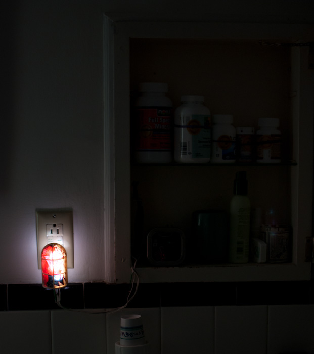
When taking her battery of medicines, my mother occasionally loses — or, lost — track of which ones she had already taken. This aims to keep track of what's been taken (and how recently); and also to provide a night light, as long as it's taking up an electrical outlet.
Overview
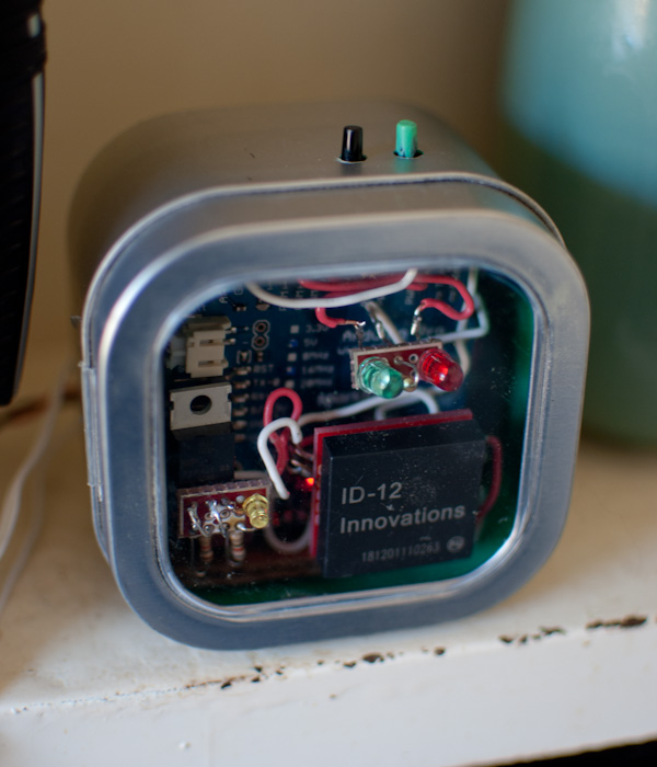
The meter consists of an Arduino connected to an RFID reader, along with various switches and LEDs and a speaker for input and feedback. An RFID tag is attached to each pill bottle. Before taking any pill, one scans the bottle; the meter either announces 'no' (it was taken too recently); or announces 'yes' and records that the pill is being taken. (An announcement is either a red or a green LED accompanied by a short melody played on the speaker.)
Code
The source code (with an overview of the files in its README) is on github.
It depends on the NewSoftSerial library to read serial data from the ID-12 using an arbitrary digital pin.
Usage(link here)
Taking Pills
For each pill to be taken, scan the pill bottle. Upon hearing the 'no' melody and seeing a red LED flash, do not take the pill (it was already taken too recently); upon hearing the 'yes' melody and seeing a green LED flash, take the pill (it is automatically marked as taken and the timestamp recorded).
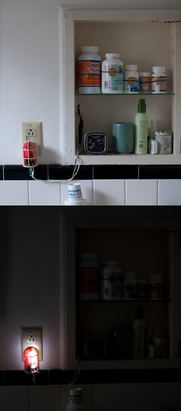
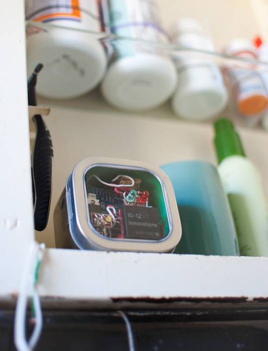
The RFID meter in the medicine cabinet with tagged pill bottles; mouse over to see night-light on
The interval (how often a pill may be taken) is set when adding. The meter allows taking a pill after 90% of its interval has elapsed; this is to allow for example a daily pill to be taken each day at roughly 8:00, as opposed to requiring exactly 24 or more hours to pass, which in practice would push the time gradually later.
Resetting
Tap the black button to forget all IDs. (Hold the black button while plugging in the meter has the same effect, and may be useful after the program is first uploaded, when the EEPROM has unknown contents.)
Adding IDs
- Tap the green button to enter add mode. The red and green LEDs flash alternately to show add mode is active, but no ID has been scanned. (Tapping the green button again at this point cancels.)
- Scan the RFID tag / pill bottle. The green LED flashes to indicate that an ID has been scanned, and to indicate at what interval it may be taken.
- Scan the tag again to change the interval:
# Green LED Blinks Interval (hours) 1 24 (daily) 2 12 (twice daily) 3 4 (for 'every 4-6h' pills) - Tap the green button again to finish adding the ID.
- When scanned immediately after adding, a pill will be approved for taking.
Power Interruption (Unplugging)
When the meter is power cycled (unplugged and plugged back in), it forgets when pills were last taken, but remembers the ID tags and associated intervals. The ID and associated interval are immediately written to EEPROM when newly added, but the timestamp is stored only milliseconds since the meter was last turned on and cannot be meaningfully saved (see improvements). When starting back up it assumes all pills have just been taken, to guard for example against a brief power outage resulting in overdose. (Re-adding a pill will clear its last-taken time.)
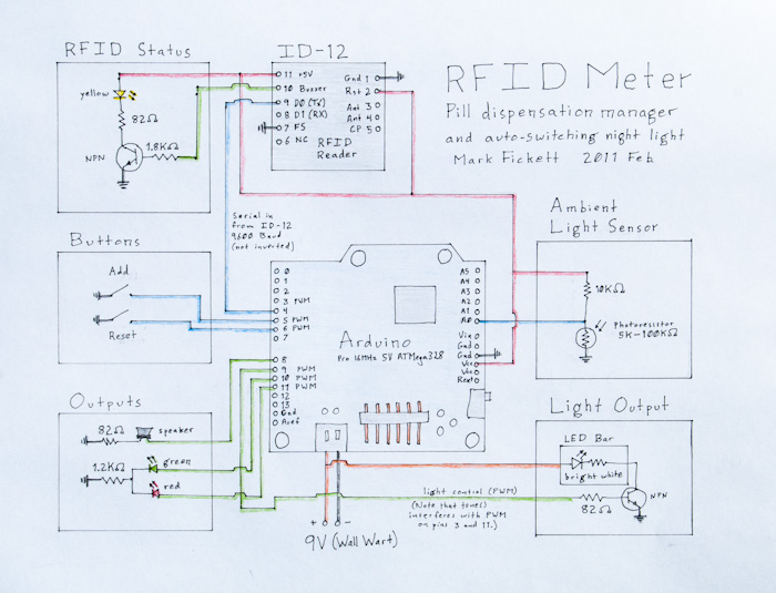
Parts and Circuit(link here)
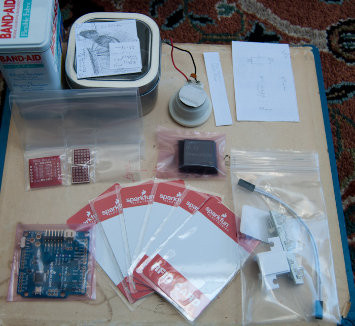
Parts List(link here)
- Arduino Pro 5V (SparkFun / $20), used with 5V FTDI (USB/Serial adapter; SparkFun / $15)
- Innovations ID-12 125kHz (LF) RFID reader; see below (SparkFun / $30)
- ID-12 Breakout from SparkFun (95$cent;)
- SparkFun 125kHz RFID cards ($2 each) (eventually replaced by the following, for convenience)
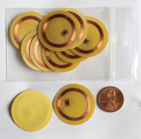
- 3cm diameter sticker-backed RFID tags, 125kHz / EM 4102 (Trossen Robotics / $1 each)
- 5x5 pin boards for buttons, LEDs, sub-circuits (SparkFun / 50¢ each); cut in half as used
- Bright White LED Bar (SparkFun / $4)
- Various resistors (from SparkFun's resistor kit, $10 for several hundred)
- Jumper wire with JST connector (SparkFun / 95¢), connected to a 9V wall wart (scavenged from a cordless phone)
- LEDs from discarded electonics (VCR, cordless phone handset)
- Speaker (from a cordless phone handset; with attached capacitor)
- Buttons (push-buttons, NO) (from a VCR)
- Enclosure (among our small-containers repository, chosen for size and having a nonmetallic window in the lid)
- Breadboard and hookup wire for prototyping; soldering iron, wire strippers, needle nose pliars, liquid electrical tape (to color button, insulate wire joints, and for enclosure interior), etc
The ID-12 requires 5V, thus the choice of the 5V Arduino Pro. The choice of the ID-12 itself was somewhat arbitrary (and a MIFARE reader might provide greater compatability with other projects), but was a convenient all-in-one item with compatible cards from the same vendor; however, I ended up switching to 3cm-diameter adhesive tags from Trossen since they fit pill bottles better.
Construction
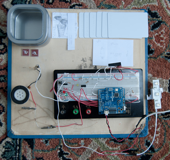
Breadboard work-in-progress, nearly final; see circuit
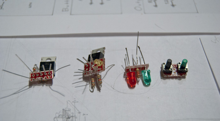
Button, LED, and sub control boards ready to be soldered; button boards scored with a plastic cutter and then broken over a metal edge
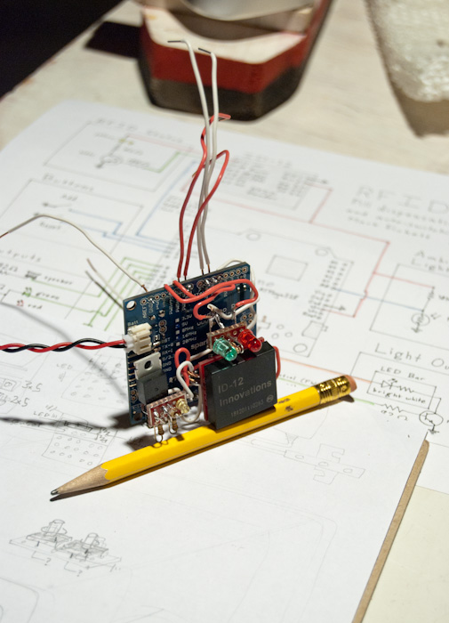
The Arduino with the ID-12, LED, and scan-feedback boards
I ordered the parts on February 17th, and — working on it intermittently, replacing a USB/Serial adapter I broke, testing over a few days — installed it in its enclosure in the medicine cabinet March 7th (a little over two weeks later). The enclosure construction and soldering step was a one-day project.
ID-12 / RFID Notes(link here)
The ID-12 documentation is far from verbose (except for antenna construction, only required for the leaner ID-2). I found Martin Rädlinger's notes, and his and others' code very helpful, though I ended up significantly modifying the code to provide a simpler interface (just hasID() and getID(buffer)).
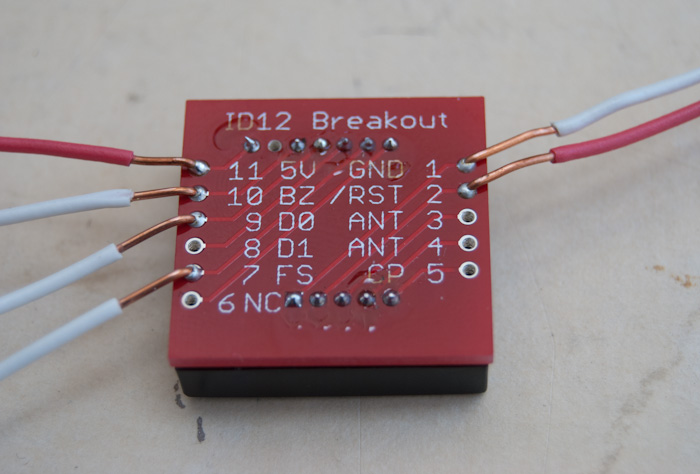
ID-12 with the SparkFun breakout board and hookups used for the meter
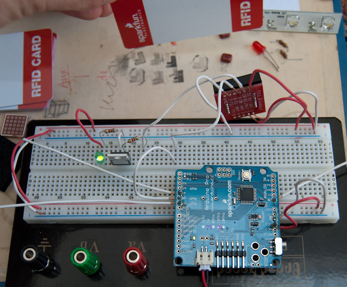
ID-12 with Arduino test circuit, showing the green LED lit in response to a card recognition
ID-12 Connections:
| 1 | Ground | Connect to ground. |
|---|---|---|
| 2 | Reset | Connect this to +5V for normal operation. The unit does not function with it connected to ground. Martin manipulates it, but I had no need. |
| 3 | Antenna | Unused (the ID-12 has an internal antenna, though presumably this could be augmented). |
| 4 | Antenna | Unused. |
| 5 | CP | Unused. |
| 6 | NC | Unused |
| 7 | Format Select | Connect this to ground for ASCII output over serial. |
| 8 | D1 | RX; Unused. |
| 9 | D0 | TX; Sends data at 9600 baud. |
| 10 | Buzzer | Turns on briefly (and oscillates) when an RFID tag is detected. Connect this to the base of a transistor to control an LED, or to a speaker for a beep. |
| 11 | +5V | Connect to +5V. |
The output of the ASCII format over serial is, as outlined by Elio Bidinost:
| Description | start | data | checksum (xor of data chars) | line endings | end | |
|---|---|---|---|---|---|---|
| Detail | STX | 10 chars | 2 chars | CR | LF | ETX |
| ASCII | 02 | number or uppercase letter | 13 | 10 | 03 | |
(See also, ASCII control codes.)
When NewSoftSerial initially reports that there is data available(), not all of it is yet there; my solution is to delay() slightly, then read all the characters at once (rather than poll repeatedly for more data).
The ID-12 and cards from SparkFun operate at 125kHz, and are listed as using the EM 4001 standard. I haven't found a definitive source, but it appears members of the EM 41x family may all be cross-compatible; various sources say EM 4102 is the current LF standard, and the ID-12 does also read tags listed as EM 4102 (see parts, above).
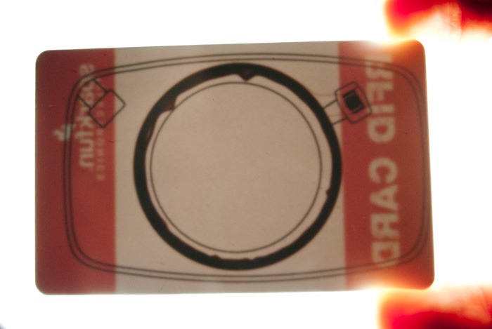
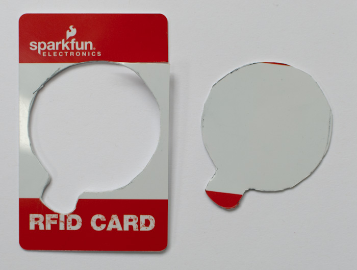
The SparkFun RFID card, strongly backlit and showing internals
The SparkFun card looks similar to a dual-frequency RFID card, but appears not to have a chip connected to the outer antenna (and is not recognized by a NFC scanner in a Nexus S). Moreover, I was able to cut out the innner ring and chip and still have a working card.
See also visualizing the shape of the readable volume of the ID-20.
Improvements and Feedback(link here)
See also (or contribute to) the arduino.cc forum topic.
- Timestamps for when a pill was taken are based only on
millis()(milliseconds since the Arduino started up), so when the meter loses power it no longer knows when things were taken. A real-time clock or other self-powered timing unit could solve this. - The blinking for feedback while adding a new ID interferes with button reading (particularly: the triple-blink for a 4h interval blocks long enough that a button press to signal adding is complete is sometimes missed). A non-blocking blinking routine (such as a non-blocking Morse library, though that seems overkill) could fix this.
- Since the meter resides in a medicine cabinet, it could have a contact switch (for example) to detect when the door is closed, and turn off the RFID reader in that case, saving (minimal) power.
- The final construction and enclosure could bear revision; particularly, the button board is supported only by wires — nothing is screwed to the case.
- The idea could be ported fairly easily to a smartphone app, using the barcodes on the pill bottles or using Near field communication and compatible RFID tags.
- The user must remember to scan the bottle before taking the pill. Valalvax suggests putting a mechanical sensor on the pill holder (which equates taking with opening the holder instead of swiping; still not perfect, but cannot be forgotten).
- LEDs and tones are minimally informative; defsdoor suggests adding a text display for when the pill was last taken, or what interval is selected.
Backlinks
- Posted on the Arduino blog and The Special Day 4 Me (March 25th
- Silicon Maniacs (French), March 28th.